Diagrams
Diagrams are fundamental artifacts of design.
Systems can be complex things.
As such they are difficult to apprehend in a single vision.
Many perspectives are necessary to comprehend all of a system's aspects.
Importance of Diagrams
Much of system design consists of diagrams that portray an aspect of a system such as how parts are connected, when things happen and how goals are accomplished.
One might think that there is a system diagram that could convey all the relevant aspects of a system to developers.
Well it hasn't been discovered yet.
Instead many types of diagrams have been competing for attention.
In the last few years there has been some convergence.
The current set of acceptable diagrams are included in the Universal Modeling Language (UML).
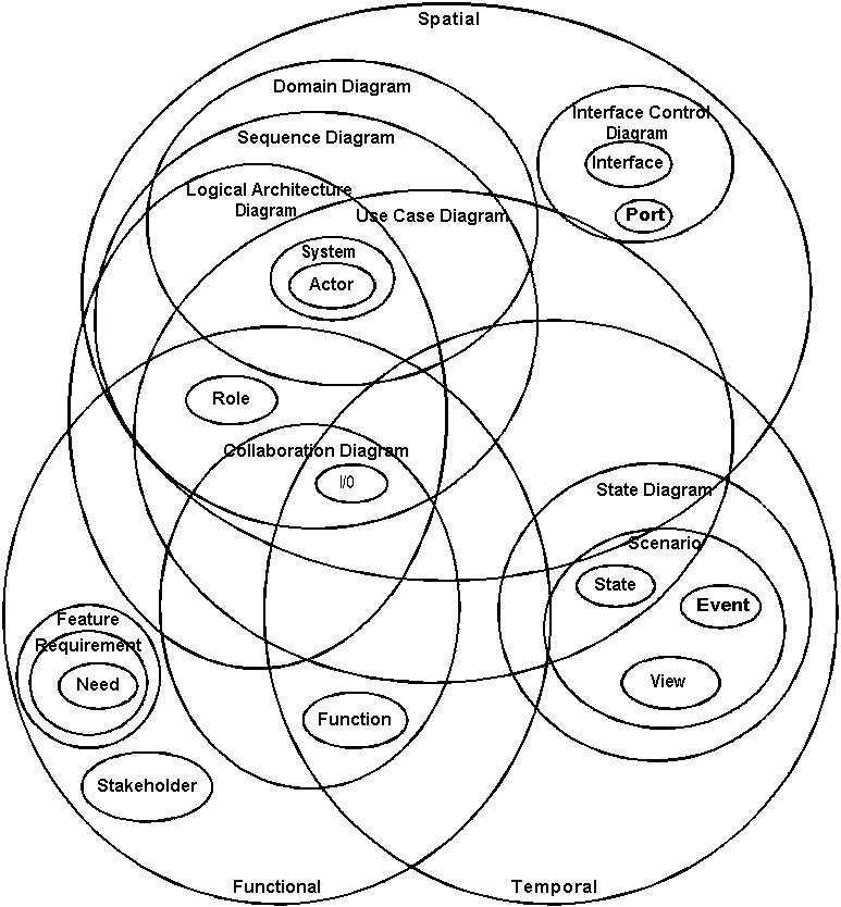
Taxonomy
The following SE Taxonomy diagram illustrates the content included in the various diagram types.

So pick a diagram type that appears to embody the type of information that is of current interest.
Then realize that depending on the complexity of the system some possibly all the other diagrams may be necessary to convey the types of information that will be needed later.
Finally many of the diagrams contain information that must be reconciled to the other diagram types.
See
Process Diagrams for information contained in various diagram types.
Important Diagrams
The following diagram types are used by systems engineers at various stages of development;
Use Case, Logical Architecture,
Sequence,
STD, ER, Collaboration, Activity, Deployment and
Environment.
Diagrams not depicted elsewhere are described here.
Logical Architecture
The Logical Architecture diagram shows the top level components of a system with all their internal and external interfaces named and lines between communicating components and actors.
ER
There are many types of Entity Relationship diagrams.
Chen envisioned a system where data tables are illustrated as boxes and the relationships among them are illustrated first by diamonds then later by variously decorated lines. ER diagrams are used by designers to model persistent information. All information is either things called
Entities or
Relationships among them.
Collaboration
A Collaboration diagram is similar to a sequence diagram except that the time information is not so evident.
In fact a collaboration diagram shows all possible communications among systems while a sequence diagram only shows a subset of interesting sequences.
Activity
Activity diagrams are a variant of STDs that can represent complex instantiation of objects.
Deployment
A deployment diagram shows how equipment will be positioned when installed.
Back | Next |
Process Diagrams | Use Case
Copyright Spidel Tech Solutions, Inc. 2004 All Rights Reserved. Updated:
7/11/2009 12:15:52 AM
Idx: 1131 Site Design STS

 So pick a diagram type that appears to embody the type of information that is of current interest.
Then realize that depending on the complexity of the system some possibly all the other diagrams may be necessary to convey the types of information that will be needed later.
Finally many of the diagrams contain information that must be reconciled to the other diagram types.
See Process Diagrams for information contained in various diagram types.